TERMINALS
Introduction
Terminals are used for specifying the interface to a circuit. Proteus does not allow a wire to 'float', so both ends must connect to something and every input and output in your design will be indicated by a terminal.
Terminals fall into two kinds, Logical Terminals and Physical Terminals, distinguished purely by the syntax of their labels. Test point terminals are a special case of the physical kind and are described under Placing Terminals below.
You can customise the appearance of terminals by editing the TERMINAL graphics style as shown below. See Global Styles for more information.
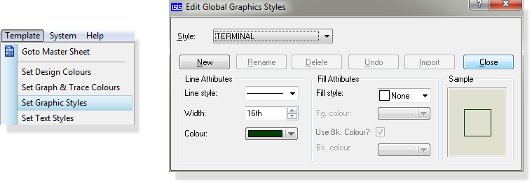
Editing the TERMINAL graphics style in the Edit Global Graphics Styles dialogue
The dialogue above is opened with the Set Graphic Styles command on the Template menu. See Set Graphic Styles for the controls on the form.
Logical Terminals
A logical terminal serves merely to donate a net name to the wire to which it connects. Groups of wires with one or more net names in common are taken to be connected by the netlist generator. Logical Terminals thus provide a means to connect things together without using wires. In particular they provide the means to make connections between the sheets in a multi-sheet design.
As with Wire Labels and Bus Entries, the net name can contain any alphanumeric characters plus the hyphen ('-') and underscore ('_'). Spaces can be used within PROTEUS but may cause problems for other software.
Logical terminals may also connect to buses. This provides an extremely efficient way to run buses up and down a hierarchical design.
See Net Names for discussion of the role of logical terminals in netlisting.
Logical terminals are vital to connectivity in multi-sheet designs. If you are using sub-circuits or working with sizeable schematics please refer to the section on Hierarchical Designs for more information.
See Connecting NC Pins for information on using NC terminals to indicate NC status on component pins.
Physical Terminals
A physical terminal represents a pin on a physical connector. For example, a terminal with the name:
J3:2
is taken to be pin 2 of connector J3. Whilst it is perfectly possible to deal with connectors in exactly the same way as all other components (i.e. define a device to represent them), using Physical Terminals has the advantage that the pins can be placed wherever it is most convenient.
Physical terminals will appear as parts in the parts bin of the layout module and are then packaged when you place them on the board.
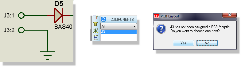
Physical terminals on the schematic and the parts they produce in the layout parts bin
Alternatively, you can specify the package type for the part with a FIELD property assignment block, since there is no actual component to edit. See Part Property Assignments (*FIELD) for the syntax.
Note that a bus terminal may not be physical, as there is no means to specify the pin numbering for the individual pins.
Placing Terminals
Proteus supports an unlimited variety of terminal symbols. However, when you first select the Terminal icon, a basic set of 12 types is automatically pre-loaded into the Object Selector:
| Terminal Type | Purpose |
| DEFAULT | A plain terminal with no electrical type of its own. It is treated as passive. |
| INPUT | A terminal declared to the netlist compiler as an input. |
| OUTPUT | A terminal declared to the netlist compiler as an output. |
| BIDIR | A terminal declared to the netlist compiler as bidirectional. |
| POWER | A supply terminal, whose net becomes a power rail. |
| GROUND | A supply terminal drawn with the ground symbol. |
| CHASSIS | A supply terminal drawn with the chassis symbol, for a chassis or earth connection. |
| RETURN | A supply terminal drawn with the signal return symbol. |
| DYNAMIC | A terminal which binds to a part in the layout in the same way as a physical terminal. |
| BUS | A terminal for connecting to a bus. A bus terminal may not be physical. |
| TESTPOINT | A test point. Unlike every other terminal it carries a reference rather than only a net name, and it reaches the PCB as a part in its own right. |
| NC | Marks a pin as deliberately not connected. An NC terminal cannot be placed on a net. |
To place a terminal:
- If the terminal type you want is not listed in the Object Selector, first pick it from the symbol library.
- Highlight the terminal name in the Object Selector. Proteus will show a preview of the terminal in the Overview Window.
- Use the Rotation and Mirror icons to orient the terminal appropriately.
- Left click the mouse on the Editing Window to enter placement mode and the move the mouse to the position where you want to place the terminal.
- Left click the mouse again at this point to commit the changes and exit placement mode.
Having placed a terminal, you must then annotate it since an unannotated terminal will be ignored by the netlist compiler. There are a variety of approaches:
- Edit the terminal label using any of the general methods described in Editing an Object.
- Select the terminal label from the drop down combo box. This list contains all the existing named nets on the current design.
- Use the Property Assignment Tool to assign the NET property of one or more terminals. This is especially effective if a group of terminals have names which run in an alphanumeric sequence.
It is quite legal to connect buses to terminals. In this case, the name for the terminal should generally define the range for the bus, as in D[0..7], although this is not mandatory. If no range is given, Proteus will use the range given for the bus section that connects to the terminal, or if that has no name or range then the width will be taken from whatever bus pins connect to the bus.
Placing a terminal without annotating it will be reported as a netlist error since such an object has no meaning, logically or physically.
Test Points
A test point terminal is the one exception to the rule above, because it is annotated for you. When you place one, Proteus gives it a reference of the form TP1, TP2 and so on, and continues the sequence for each further test point you place. Since it carries a reference rather than a net name, a test point appears in the layout parts bin as a part in its own right and is packaged there in the same way as a physical terminal.
NC Terminals
An NC terminal marks a component pin as deliberately not connected. It cannot be given a net name, and an attempt to assign one is refused.
See Connecting NC Pins for how NC status is carried through to the layout.
Editing Terminals
A terminal may be edited using any of the general editing techniques (see Editing an Object). For your convenience with logical terminals a list of existing named nets is available as a drop down combo box allowing you to easily specify the net name.
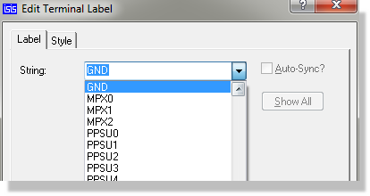
The Edit Terminal dialogue form showing a drop down list of net names
In addition, since terminals often appear in groups, the Property Assignment Tool can be put to good use for annotating and setting the electrical type of terminals.
Terminal Properties
Terminals have the following system properties:
| Property Name | Description |
| NET | The terminal net label. |
| SYMBOL | The symbol used for the terminal. This can be one of the standard terminal types, or else the name of a user defined terminal symbol. |
| TYPE | The electrical type of the terminal. This can be any of PASSIVE, INPUT, OUTPUT, BIDIR or POWER. |
| LOCKED | Set this to lock the terminal name against further editing. |
| REF | The test point reference. This applies to test point terminals only. |
See Also: